- 您现在的位置:买卖IC网 > Sheet目录2001 > ISL26134AVZ (Intersil)IC ADC 24BIT SRL 80SPS 28TSSOP
ISL26132, ISL26134
17
FN6954.1
September 9, 2011
Standby Mode Operation
The ADC can be put into standby mode to save power. Standby
mode reduces the power to all circuits in the device except the
crystal oscillator amplifier. To enter the standby mode, take the
SCLK signal high and hold it high after SDO/RDY falls. The
converter will remain in standby mode as long as SCLK is held
high. To return to normal operation, take SCLK back low and wait
for the SDO/RDY to fall to indicate that a new conversion has
standby mode.
Supply currents are equal in Standby and Power-down modes
unless a Crystal is used. If the Crystal is used, the Crystal
amplifier is turned ON, even in the standby mode.
Performing Offset Calibration After Standby
Mode
To perform an offset calibration automatically upon returning
from standby, deliver 2 or more additional SCLKs following a
data read cycle, and then set and hold SCLK high. The device will
remain in Standby as long as SCLK remains high. A calibration
cycle will begin once SCLK is brought low again to resume
normal operation. Additional time will be required to perform the
illustrate the details of performing offset calibration after
standby mode.
TABLE 12. STANDBY MODE TIMING
PARAMETER
DESCRIPTION
MIN
MAX
UNITS
t9
SCLK High after
SDO/RDY Low
SPEED = 1
0
12.44
ms
SPEED = 0
0
99.94
t10
Standby Mode Delay
SPEED = 1
12.5
SPEED = 0
100
t11
SDO/RDY falling edge
after SCLK Low
SPEED = 1
50
60
SPEED = 0
400
410
TABLE 13. OFFSET CALIBRATION TIMING AFTER STANDY
PARAMETER
DESCRIPTION
MIN
MAX
UNITS
t12
SDO/RDY Low after
SCLK Low
SPEED = 1
108
113
ms
SPEED = 0
808
813
ms
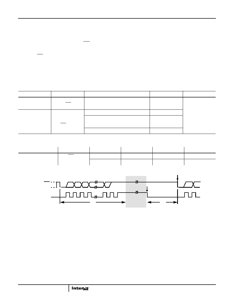
FIGURE 34. OFFSET CALIBRATION WAVEFORMS AFTER STANDBY
SDO/RDY
SCLK
23
22
21
0
124
25
STANDBY MODE
DATA READY AFTER CALIBRATION
23
BEGIN
CALIBRATION
t12
t10
发布紧急采购,3分钟左右您将得到回复。
相关PDF资料
ISL26319FVZ-T7A
IC ADC 12BIT SRL/SPI 16TSSOP
ISL26329FVZ
IC ADC 12BIT SPI/SRL 16-TSSOP
ISL2671286IBZ
IC ADC 12BIT SPI/SRL 20K 8SOIC
ISL26712IRTZ
IC ADC 12BIT SAR 1MSPS 8-TDFN
ISL267450AIUZ
IC INTERFACE
ISL267817IUZ
IC INTERFACE
ISL32272EIVZ-T
IC TX RS422 QUAD 16TSSOP
ISL32273EIVZ
IC RCVR RS485/422 QD ESD 16TSSOP
相关代理商/技术参数
ISL26134AVZ-T
功能描述:模数转换器 - ADC ISL26134AVZ LW-NOISE 24-BIT TI-COMP D/S RoHS:否 制造商:Texas Instruments 通道数量:2 结构:Sigma-Delta 转换速率:125 SPs to 8 KSPs 分辨率:24 bit 输入类型:Differential 信噪比:107 dB 接口类型:SPI 工作电源电压:1.7 V to 3.6 V, 2.7 V to 5.25 V 最大工作温度:+ 85 C 安装风格:SMD/SMT 封装 / 箱体:VQFN-32
ISL26134AVZ-T7A
功能描述:模数转换器 - ADC ISL26134AVZ LW-NOISE 24BIT DELTASIGMA ADC RoHS:否 制造商:Texas Instruments 通道数量:2 结构:Sigma-Delta 转换速率:125 SPs to 8 KSPs 分辨率:24 bit 输入类型:Differential 信噪比:107 dB 接口类型:SPI 工作电源电压:1.7 V to 3.6 V, 2.7 V to 5.25 V 最大工作温度:+ 85 C 安装风格:SMD/SMT 封装 / 箱体:VQFN-32
ISL26310
制造商:INTERSIL 制造商全称:Intersil Corporation 功能描述:12-bit, 125kSPS Low-power ADCs with Single-ended and Differential Inputs and Multiple Input Channels
ISL26310FBZ
功能描述:IC ADC 12BIT SPI/SRL 125K 8SOIC RoHS:是 类别:集成电路 (IC) >> 数据采集 - 模数转换器 系列:- 产品培训模块:Lead (SnPb) Finish for COTS
Obsolescence Mitigation Program 标准包装:250 系列:- 位数:12 采样率(每秒):1.8M 数据接口:并联 转换器数目:1 功率耗散(最大):1.82W 电压电源:模拟和数字 工作温度:-40°C ~ 85°C 安装类型:表面贴装 封装/外壳:48-LQFP 供应商设备封装:48-LQFP(7x7) 包装:管件 输入数目和类型:2 个单端,单极
ISL26310FBZ-T
功能描述:IC ADC 12BIT SPI/SRL 125K 8SOIC RoHS:是 类别:集成电路 (IC) >> 数据采集 - 模数转换器 系列:- 产品培训模块:Lead (SnPb) Finish for COTS
Obsolescence Mitigation Program 标准包装:250 系列:- 位数:12 采样率(每秒):1.8M 数据接口:并联 转换器数目:1 功率耗散(最大):1.82W 电压电源:模拟和数字 工作温度:-40°C ~ 85°C 安装类型:表面贴装 封装/外壳:48-LQFP 供应商设备封装:48-LQFP(7x7) 包装:管件 输入数目和类型:2 个单端,单极
ISL26310FBZ-T7A
功能描述:IC ADC 12BIT SPI/SRL 125K 8SOIC RoHS:是 类别:集成电路 (IC) >> 数据采集 - 模数转换器 系列:- 产品培训模块:Lead (SnPb) Finish for COTS
Obsolescence Mitigation Program 标准包装:250 系列:- 位数:12 采样率(每秒):1.8M 数据接口:并联 转换器数目:1 功率耗散(最大):1.82W 电压电源:模拟和数字 工作温度:-40°C ~ 85°C 安装类型:表面贴装 封装/外壳:48-LQFP 供应商设备封装:48-LQFP(7x7) 包装:管件 输入数目和类型:2 个单端,单极
ISL26311
制造商:INTERSIL 制造商全称:Intersil Corporation 功能描述:12-bit, 125kSPS Low-power ADCs with Single-ended and Differential Inputs and Multiple Input Channels
ISL26311FBZ
制造商:Intersil Corporation 功能描述:ISL26311FBZ 12-BIT, 125KSPS, SINGLE CH/ENDED DIFFERENTIAL SA - Rail/Tube 制造商:Intersil Corporation 功能描述:IC ADC 12BIT SPI/SRL 125K 8-SOIC